Your product is subjected to thermal and vibration stresses to confirm its non-operational as well as operational levels. The tests verify the product's survival during the non-operating (shipping and storage) conditions. They also verify that the product meets or exceeds its design operational limits. Descriptions of a sample of environmental tests performed.
Baxter Reliability Laboratory
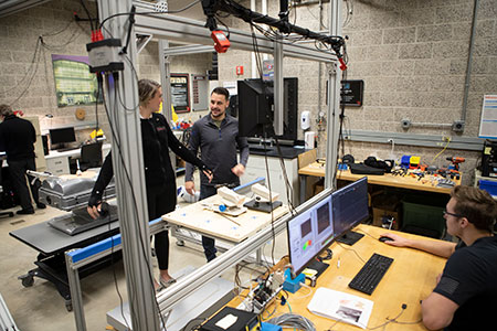
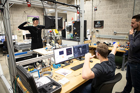
The Baxter Reliability Laboratory is equipped to meet thermal, vibration and functional test requirements. External customers may provide their own specific test requirements. The laboratory is equipped to handle a variety of product validation requirements, product robustness testing (HALT), electrical stress testing, and accelerated life testing. Additional Reliability functions provided include thermal analysis, reliability prediction, and warranty calculations.
Areas of Expertise
This test exposes the product to severe temperature extremes in rapid succession. For example, the product is transferred from an extreme hot environment to an extremely cold environment. This process is repeated several times. It is similar to temperature cycling, but more severe and may involve different failure mechanisms. Baxter Reliability uses an air-to-air system for product testing. Air-to-air thermal shock testing employs a high rate of temperature change, typically 30°C per minute or higher. Baxter Reliability can do this with a single chamber using liquid nitrogen (LN2) or a two chamber approach where one chamber is hot and the other is cold. The variables for shock test include hot & cold temperatures, dwell times at each temperature, maximum time required to move the product from one chamber to another, and the number of cycles (one cycle = one hot and cold dwell).
Result: a cost-effective way to screen defects at the component level; particularly in integrated circuits which require a high degree of stress to experience the rates required to force latent defects into failure.
Humidity testing is typically performed in a chamber that can precisely control wet and dry temperatures. Exposing products to humidity stress precipitates corrosion and contamination defects in products. Humidity can penetrate porous materials, cause leakage between electrical conductors, and is also an important stress when evaluating coating and seals.
Typically, humidity tests are of long duration, and certain types of corrosion require minimal airflow, which is not typical of most chambers.
Result: an effective means of detecting moisture penetration in porous materials, detecting leakage between electrical conductors and evaluating coatings and seals.
Temperature Cycling consists of multiple cycles of changing temperature extremes. The temperature extremes, the ramp rates, and the dwell periods are variables used in calculating the test's screening strength. This calculation is based on MIL-HDBK-344A Section 5.4 Procedure C and includes the following test methodology:
Determining Thermal Cycling Ranges
- Investigate Bill of Materials (BOM)
- Reduce part list to components affected by thermal cycling
- Search component data sheets for thermal ranges
- Develop matrix of parts vs. thermal ranges
- Assess matrix for the most restrictive parts. If the UUT is going to be powered, do thermal survey to determine assembly hot spots
- Determine min and max thermal level. Thigh = most restrictive high temperature, Tlow = most restrictive low temperature
- Determine thermal range
- Evaluate proposed test which is a function of: chamber air velocity, dwell times, ramp rates, UUT hardware mass
- Determine stabilization and soak periods
- The UUT must be instrumented internally to help determine the thermal dwell times
- Thermal stabilization must be achieved at each temperature dwell extreme
Determine Screening Strength
- The screening strength is a function of the thermal rate of change, the temperature range, and the number of thermal cycles performed
- To carry out an effective thermal cycling, do the following: maximize the rate of change and the temperature range, and use the number of cycles to optimize the process. The number of cycles is used to achieve a target screening strength probability. **Note: Screening Strength is the percent of defects that could be found by that screening process.
- The rate of change and the temperature range are determined from the thermal matrix and from experimental test data
- The number of cycles is calculated from the screening strength formula (TR-82-87) test report.
- At card level, the screening strength is 70-80%
- At system level, the maximum screening strength is approximately 50%. This is due to the slow rate of change of cards inside the system.
Result: The constant rate of change provides the expansion and contraction necessary to sufficiently stress the product. The screening strength provides a measure of defect precipitation and detection efficiency.
Vibration testing involves stimulating a product with a pre-determined force over a frequency spectrum. Vibration forces are transferred to the product by figuring attached to the moving element of the electrodynamics shaker. The shaker is controlled by a closed loop vibration control system.
Result: Repeatable results and accurate reproduction of real world vibration (shipping and handling, and use environments). Several categories of vibration can be run on NIU's electrodynamics vibration systems such as sine, random, resonance search and dwell, shock, sine on random, random on random, and others. These stress environments may or may note be applicable depending on the product application and are therefore tailored to the product at hand.
Equipment Identification
- Manufacturer: Ling Electronics (shaker and amplifier)
- Manufacturer: Vibration Research (controller)
- Model: 612U (shaker); Model: DMA-66 (amplifier); Model: VR8500-4 (controller)
Shaker Specifications
- Vertical & Horizontal (slip plate)
- Force (sine) 6000 LBF
- Force (random) 6000 LBF
- Force (shock) 12000 LBF
- Displacement (p-p) 1.5 in
- Velocity (max) 70 in/ sec
- Acceleration (max) 120 g
- Frequency Range 5 to 3000 Hz
Amplifier Specifications
- KVA 36
- RMS Amps 300
- Peak Amps 900
- RMS Volts 120
Controller Specifications
- 1 Analog output (drive)
- 4 Analog inputs
- Software includes: Sine, Random, Sine-on-Random, Random-on-Random, Shock, Kurtosis, etc.
Highly Accelerated Life Testing (HALT) involves very high rates of thermal cycling (typically accomplished using LN2 based systems) and multi-axis hammer-table vibration. This test is coupled with very thorough product parameter monitoring to determine instantly when a failure occurs. The function of HALT is to rapidly expose a product's weakest link in terms of its design. This weak link can be fixed and the process repeated to reveal the next most likely point of failure. Repeating this cycle results in a product with greater and greater reliability. Temperature extreme testing criteria includes specifying the minimum and maximum operating temperatures plus instructions on how the device under test should be powered, loaded and monitored.
Electrical stress testing exercises a product near or at its electrical limits. Two productive types of electrical stress tests are Power Cycling and Voltage Margining. Power Cycling consists of turning product power on and off at specific intervals. Voltage Margining involves varying the product's DC rails above and below nominal levels. Both tests are performed in conjunction with specific temperature cycling profiles.
Common parameters that might be tested include, but are not limited to:
- Input Voltage
- Input Current
- Input Frequency
- Input Duty Cycle
- Power Supply Environment Testing
Our laboratory is equipped with power supply (AC and DC) environment/immunity testing. Immunity testing measures immunity against effects of power line abnormalities, instantaneous power failures, voltage fluctuations, wave form distortion and missing phases.
Use of dedicated control software in conjunction with Kikusui PCR2000 LA multifunctional AC power supply allows testing to be conducted in compliance with IEC 61000-4 standards.
Normally, this is a one-time process through which a product is stressed at a higher level than it would experience during normal use. Accelerating the use conditions in a short time span will expose latent defects that may otherwise occur much later at a customer site. ALT drives design changes needed to eliminate these causes of failure. In order to derive an accurate failure distribution based on the failure data, the UUT should be tested well beyond the infant mortality stage of the product's life distribution. This applies to mechanical and electromechanical products. For electronic products, it is acceptable to test to the edge of the infant mortality region. This region is considered to be from 3000 to 10000 actual hours. To reach this level at normal operating temperature would therefore take up to 10000 actual hours. Our policy is to design a test to run for 720 actual hours at 70°C which approximates 7000 effective hours of life. At the conclusion of this test, the derived MTBF, the probability (reliability) of operating for x amount of hours, and the percent failure rate per year will all be derived from the test results. The important point to keep in mind is that the longer the test duration the greater the confidence limits around the calculated (advertised) results.
Result: Reduction in field returns and a greatly improved MTBF and Availability predictions.
The objective of Infrared (IR) testing is to establish thermal evaluations of a product and to ensure that the product meets or exceeds the thermal design requirements. The thermal design objectives that are to be satisfied are:
- Functional Integrity, i.e., maintaining proper operating temperature will not degrade components' performance, and
- Operational Reliability, i.e., maintaining proper operating temperature in order to extend the life of the components.
To accomplish these objectives, thermal analysis may be done with the help of a thermal imaging camera. The thermal images are used to located the product hot spots and the affected components. This information along with the components' specified thermal parameters is then used to pinpoint the critical components. The results are geared to facilitate the following actions.
- Evaluate critical components (ensure junction temperatures < specifications)
- Evaluate heat sink solutions
- Evaluate airflow solutions
- Determine temperature acceleration factors (used in FIT calculations)
Result: Evaluate occurrence of critical component(s) whose elevated temperature may result in reduced operational life.
Our experts can evaluate reliability of repairable items, i.e., Mean Time Between Failures (MTBF), reliability, failure rate, availability, and downtime analysis. Definitions of these tasks are described below:
Redundancy: The existence of more than one means to accomplish a given function. Levels of redundancy are: System level (two systems in parallel), sub-system (boards), and components. Redundancy reduces mission failures but increases logistics failures. Redundancy means complexity, thus results in increased unscheduled maintenance.
MTBF: Mean Time Between Failures is a basic measure of reliability for repairable items.
Reliability: The duration or probability of failure-free performance under stated conditions.
Availability: A measure of the degree to which an item is in the operable state at the start of the mission, when the mission is called for at a random time, i.e., the probability that the equipment is down due to required maintenance action.
Downtime: Amount of time, usually in minutes, that the item is not available to perform its mission.
When preventative Maintenance is planned, the use of redundant equipment can allow for repair with no system downtime.
Preventative maintenance actions provide systematic inspection, detection, and prevention of incipient failures. This includes the scheduled replacement of items with predictable failure modes. Scheduled maintenance is preventative maintenance at prescribed points in an items life.
Contact Us
College of Engineering and Engineering TechnologyEngineering Building
590 Garden Rd, DeKalb, IL
815-753-2256
ceet@niu.edu
 Explore our lab
